What?
I recently got my hands on a FlipperZero. If you've never heard about it, it's a small open source digital/radio multitool that is packed with features.
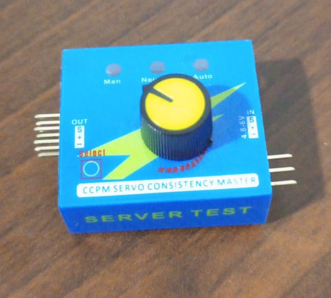
I wanted to create a servo tester app that behave similar to this one:
How are servo controlled anyway?
Servos commonly have 3 wires:
- Brown: GND
- Red: PWR
- Orange: Control
Servos are controlled by sending a PWM signal of variable width where the width of the pulse determines the position to be acheived by the servo.
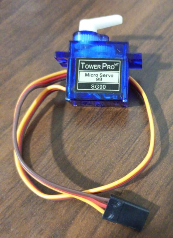
The servo I had is SG90.
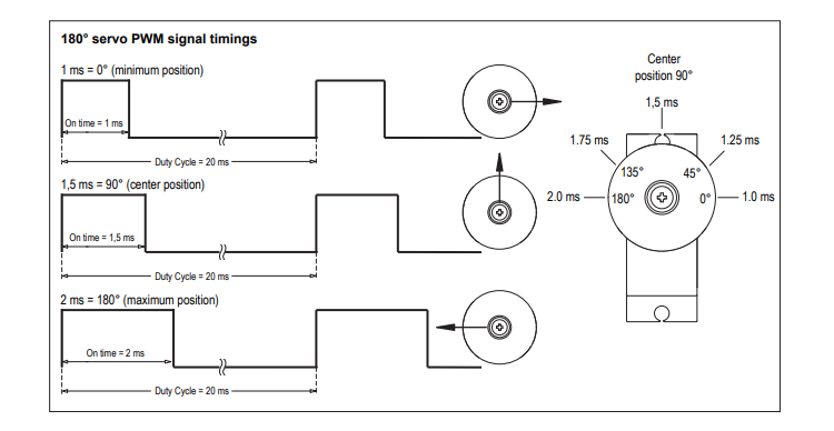
So for this servo, we have to send a pwm signal with a duty cyle 20ms (50HZ). Then based on the width of the signal (time its on) we can tell it which angle to go to.
- 1ms -> 0°
- 1.5ms -> 90°
- 2ms -> 180°
How to control using Flipper Zero
The default firmware for the Flipper already have a generator app.
The signal width generated by this app is controlled by a % of the frequency, which make it a bit tricky to have exact control of the angle of the servo.
Under the hood, the app use this api:
#include <furi_hal_pwm.h>

typedef enum {
    FuriHalPwmOutputIdTim1PA7,
    FuriHalPwmOutputIdLptim2PA4,
} FuriHalPwmOutputId;

/** Enable PWM channel and set parameters
 *
 * @param[in]  channel  PWM channel (FuriHalPwmOutputId)
 * @param[in]  freq  Frequency in Hz
 * @param[in]  duty  Duty cycle value in %
*/
void furi_hal_pwm_start(FuriHalPwmOutputId channel, uint32_t freq, uint8_t duty);

/** Disable PWM channel
 *
 * @param[in]  channel  PWM channel (FuriHalPwmOutputId)
*/
void furi_hal_pwm_stop(FuriHalPwmOutputId channel);

/** Set PWM channel parameters
 *
 * @param[in]  channel  PWM channel (FuriHalPwmOutputId)
 * @param[in]  freq  Frequency in Hz
 * @param[in]  duty  Duty cycle value in %
*/
void furi_hal_pwm_set_params(FuriHalPwmOutputId channel, uint32_t freq, uint8_t duty);
To have finer control on the width, I checked furi_hal_pwm_set_params definition:
uint32_t freq_div = 64000000LU / freq;
uint32_t prescaler = freq_div / 0x10000LU;
uint32_t period = freq_div / (prescaler + 1);
uint32_t compare = period * duty / 100;

LL_TIM_SetPrescaler(TIM1, prescaler);
LL_TIM_SetAutoReload(TIM1, period - 1);
LL_TIM_OC_SetCompareCH1(TIM1, compare);uint32_t freq_div = (64000000 / 50); // 1280000
uint32_t prescaler = freq_div / 0x10000; // 19
uint32_t period = freq_div / (prescaler + 1); // 64000
uint32_t compare = period * duty / 100; // 64000 * duty%
LL_TIM_* calls are used to instrument the STM32WB55 MCU used in the Flipper. Prescaler and AutoReload calls are used ensure that the counter fits.
For TIM1 the counter is 16-bit which mean the maximum value is 65535.
- Prescaler: specifies the prescaler value used to divide the TIM clock.
- AutoReload: Specifies the auto reload value to be loaded into the active Auto-Reload Register at the next update event.
To calculate the compare value, I calculated the value for 0° & 180°:
- 0°: 1ms signal width -> corresponds to 5% of 50HZ -> compare value 3200.
- 180°: 2ms signal width -> 10% -> 6400.
These values are set inside this function
uint32_t angle_to_compare(uint8_t angle).
Then to calculate each value I assign it a linear value from this range based on this formula:
uint32_t compare = min_compare + floor((angle / MAX_ANGLE) * (max_compare - min_compare));Usage
- Connect Servo control line to `A7` pin.
- Start app.
- If you're supplying power from a power source, make sure it have common ground with the flipper.
Controls
- Left/Right: change angle in manual mode.
- Up/Down: change mode
The app have three modes:
- Manual: left increase 10°, right dcreace 10°.
- Center: move to 90°.
- Sweep: move between 0° & 180° every 1 second.
Conclusion
Working with the Flipper was very smooth, even though there aren't many tutorials, the api's and apps are well documented and the feedback loop was fast so I was able to iterate quickly on it.
Servo's in the wild have different duty cycles / signal width, please open an issue if you want the app to support a specific model.
You can check the code in this GitHub repository.